HAM HF Vertical antenna design for DX all band operation on shortwave
This is a write-up about an antenna design I made , it is a rebuild of a secondhand 50 MHz / 6 meters antenna. This design is for HF transceiver like the popular Kenwood TR-440S-AT with build in antenna tuner. At first I just wanted to buy an antenna, antenna that I Iiked were the Sigma Eurocom SE-HF-X80 (costs around 100,-- euro) and the Comet CHA250B (400,-- euro), and discovered that most antennas for HF are easy and cheap to build yourself, my idea was to buy a old antenna (like a 27 mc type) and rebuild it.
My goal
An antenna with alloy constructed pipes, meaning less loss due to skin-effect.
An efficient (low loss) transformer.
Vertical and compact design.
Easy and automatic tuning for all frequencies: 80m 40m 30m 20m 17m 15m 12m to 10m and.
An antenna that can be simply operated and auto-tuned by any HF radio, this means an antenna impedance between 20 Ohms and 150 Ohms.
The construction
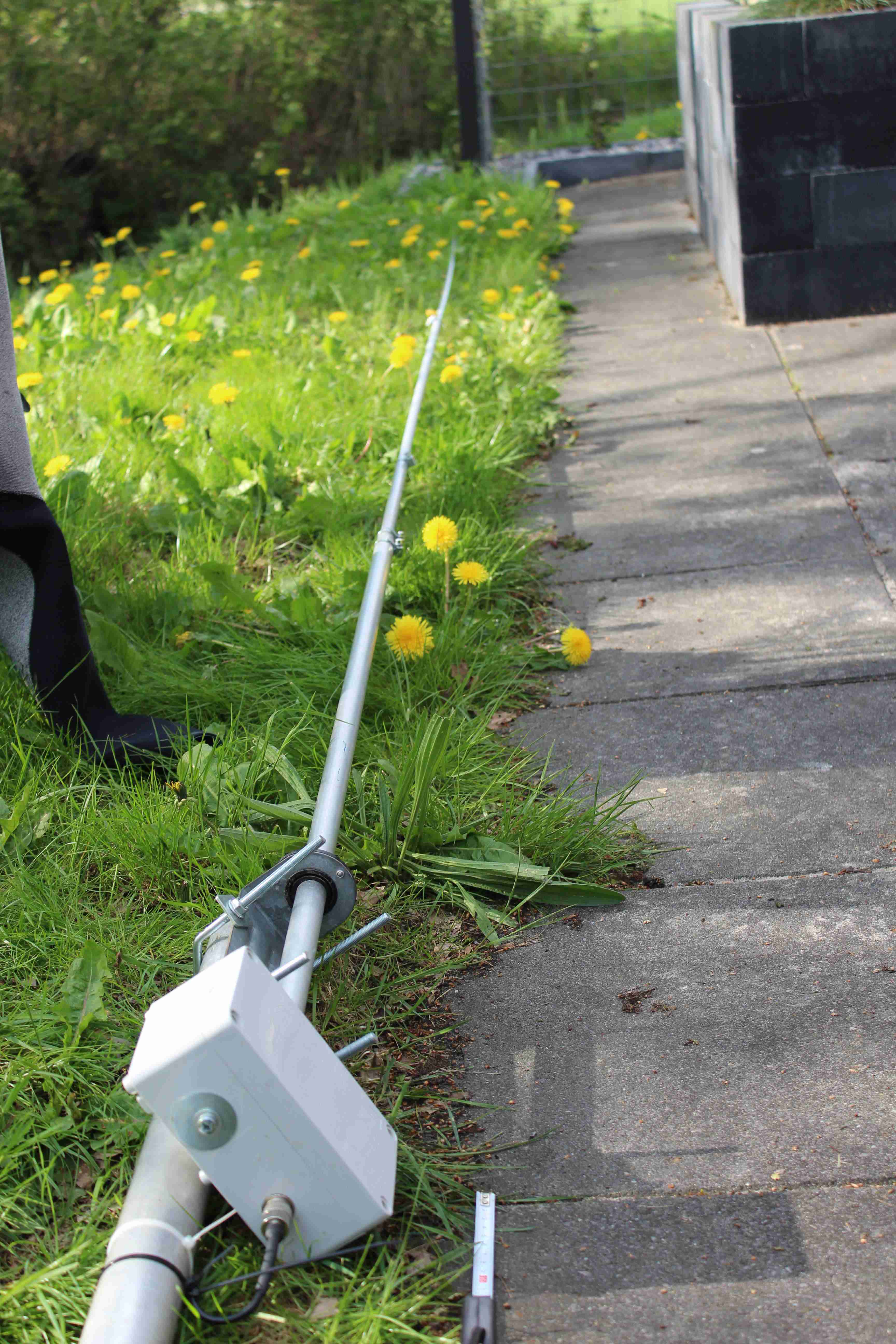
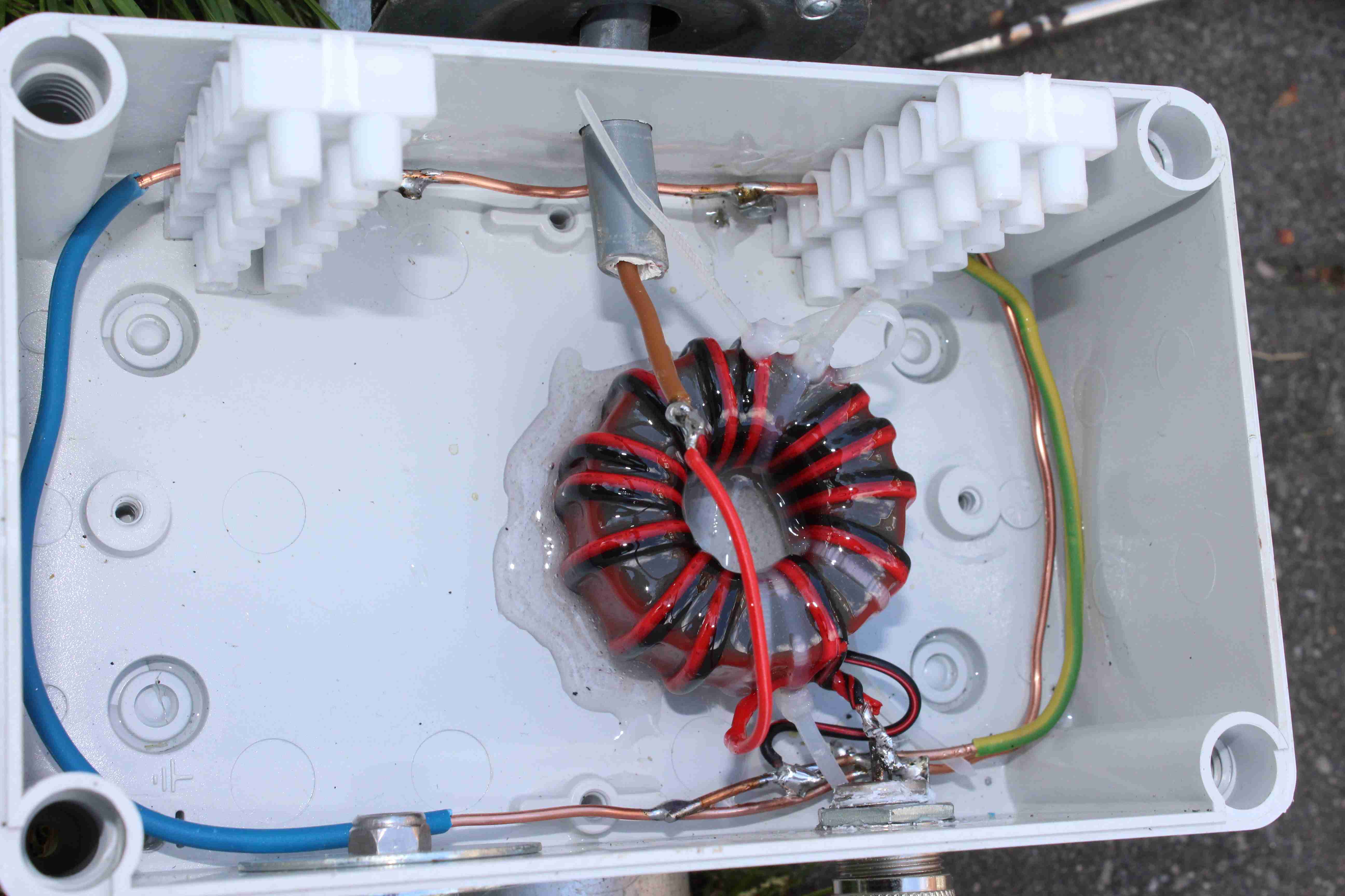
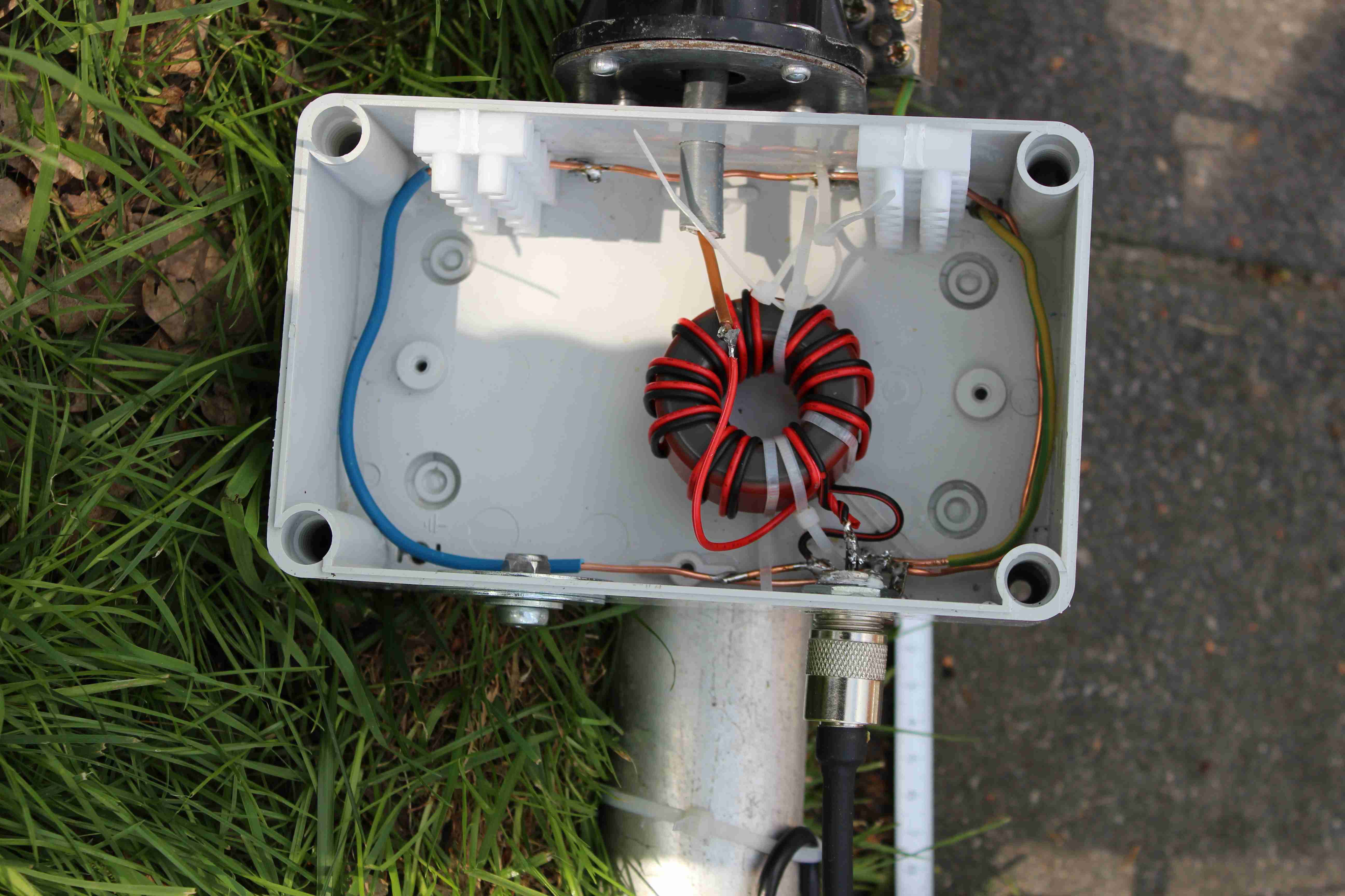
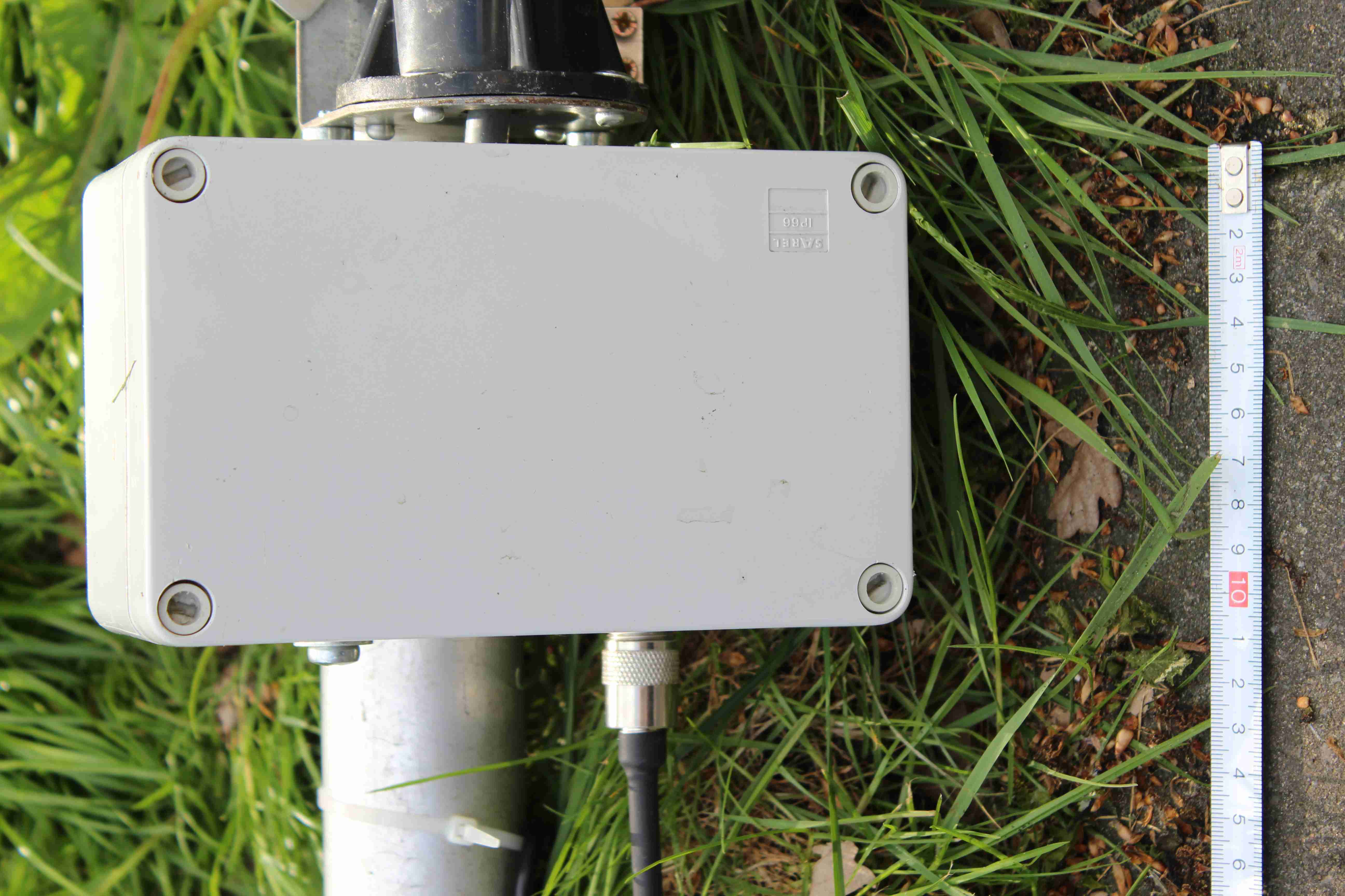
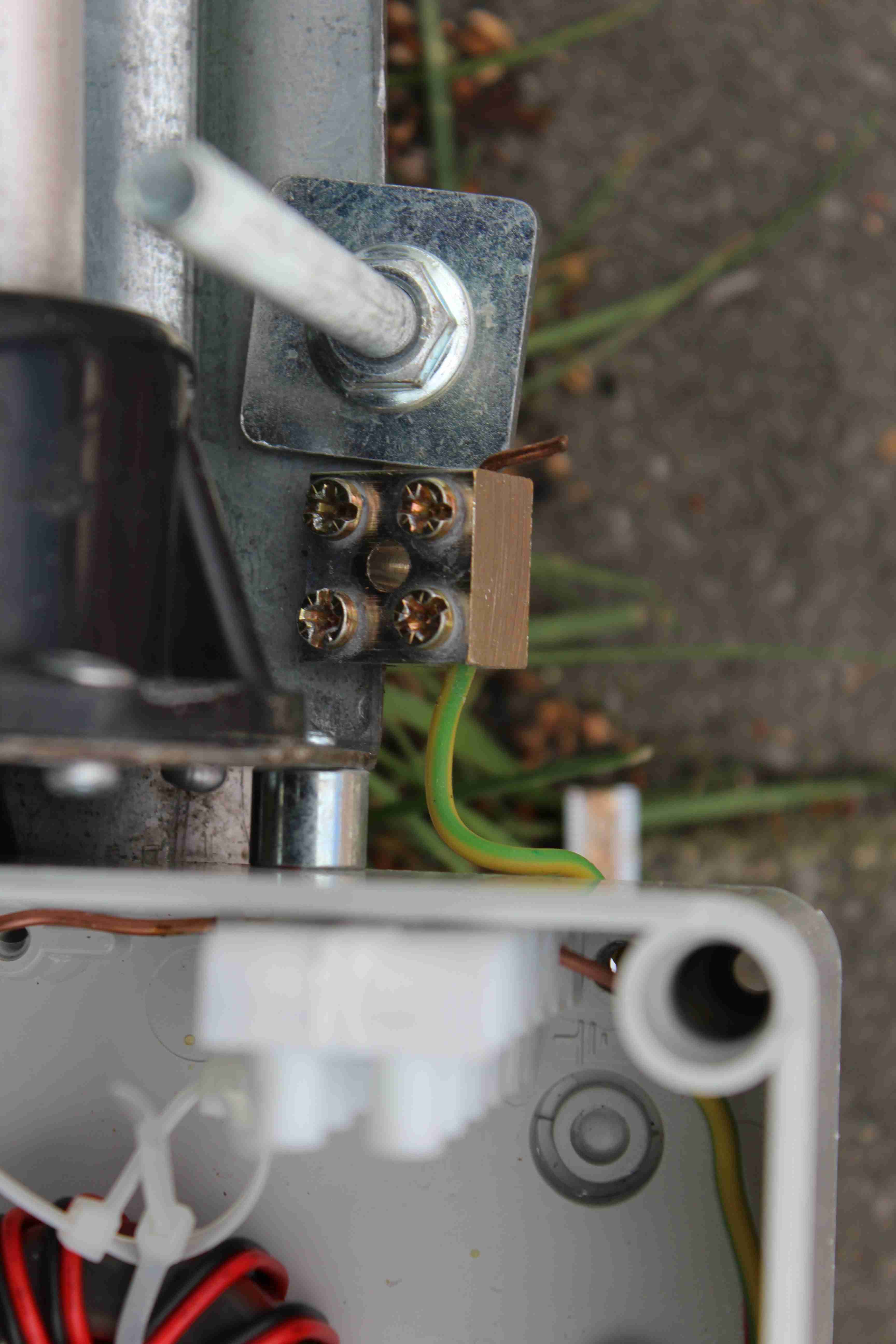
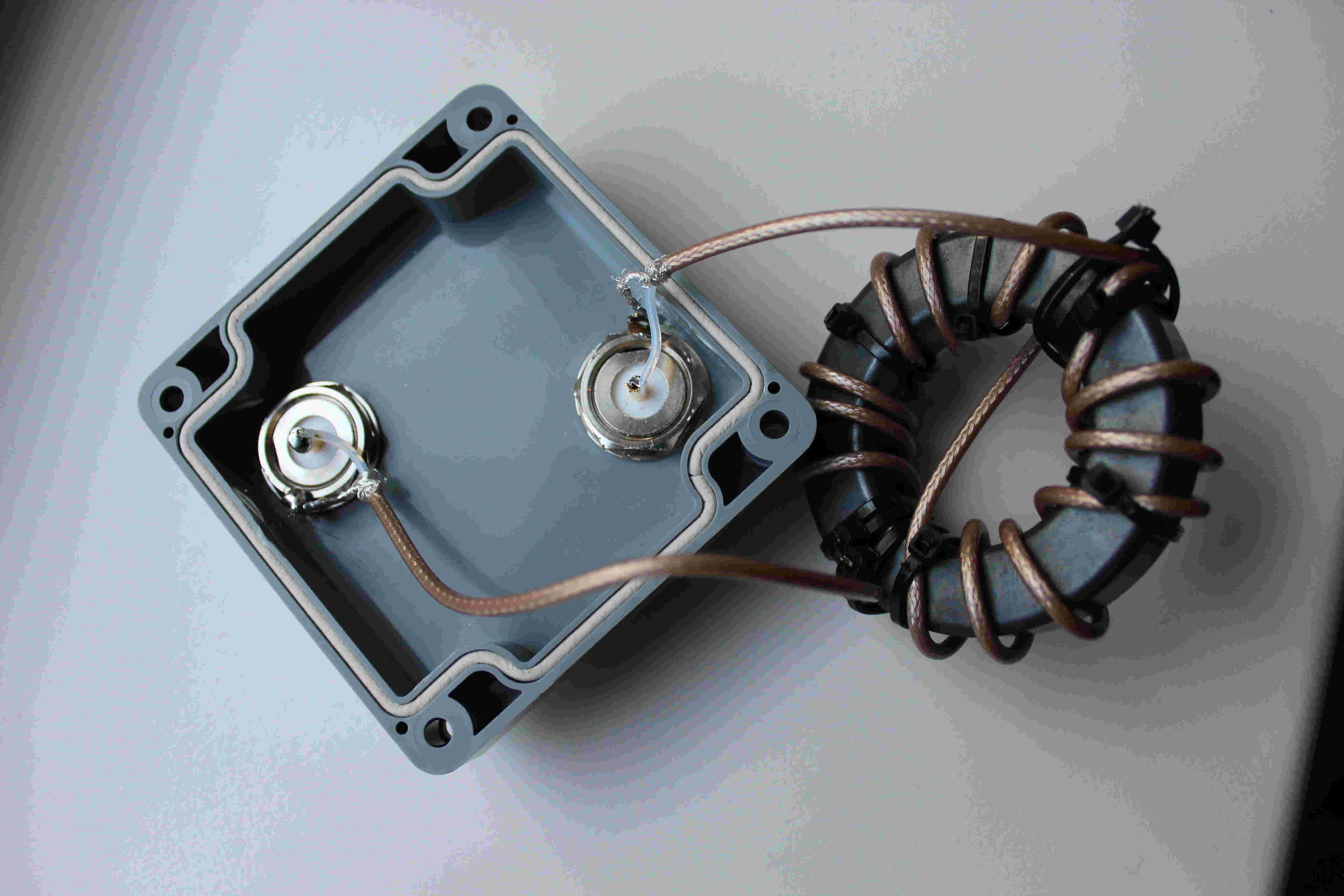
The starting point was a secondhand (10,-- euro) 50 MHz / 6 meters antenna. Two new vertical radials (2x2m long) were added and the loading coil at the base (inside the antenna base) was removed. A new transformer type UNUN 4:1 was added in a separate box at the base of the antenna.
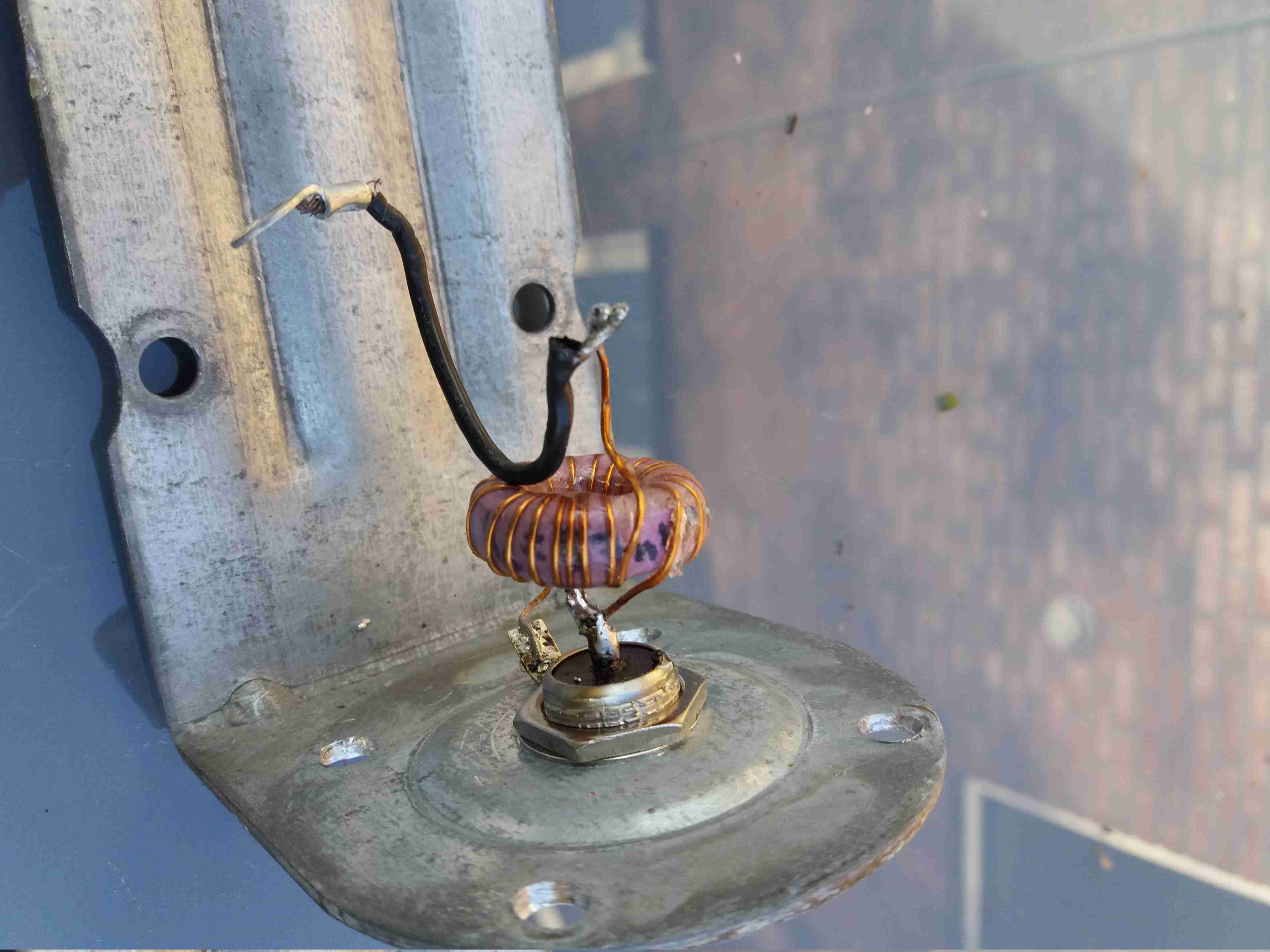
The UNUN voltage tranformer 4 to 1:
Amidon toroid core type T 184-2
13 windings bifilair (see picture)
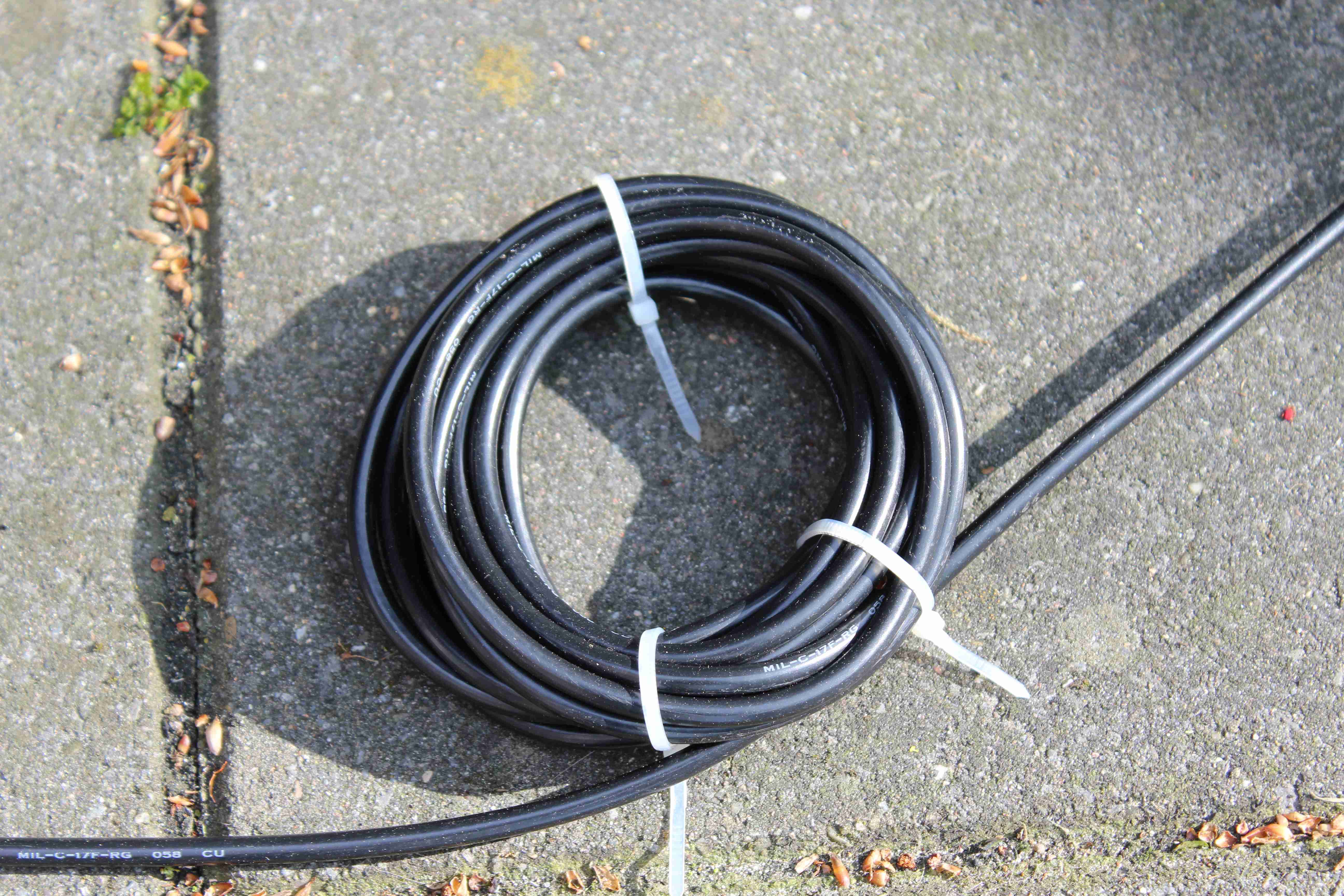
speaker cable for the 13 windings
epoxy encapsulated
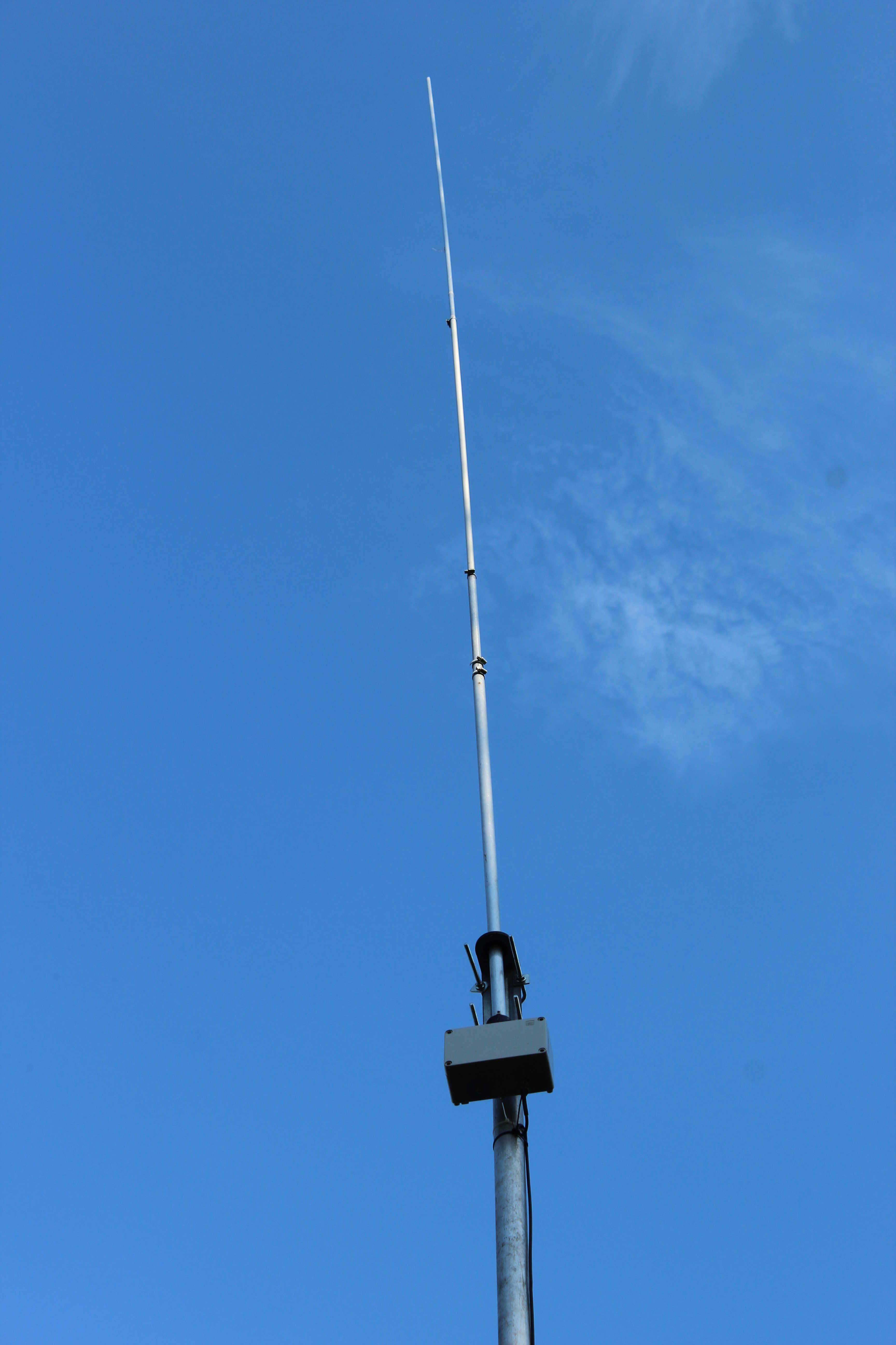
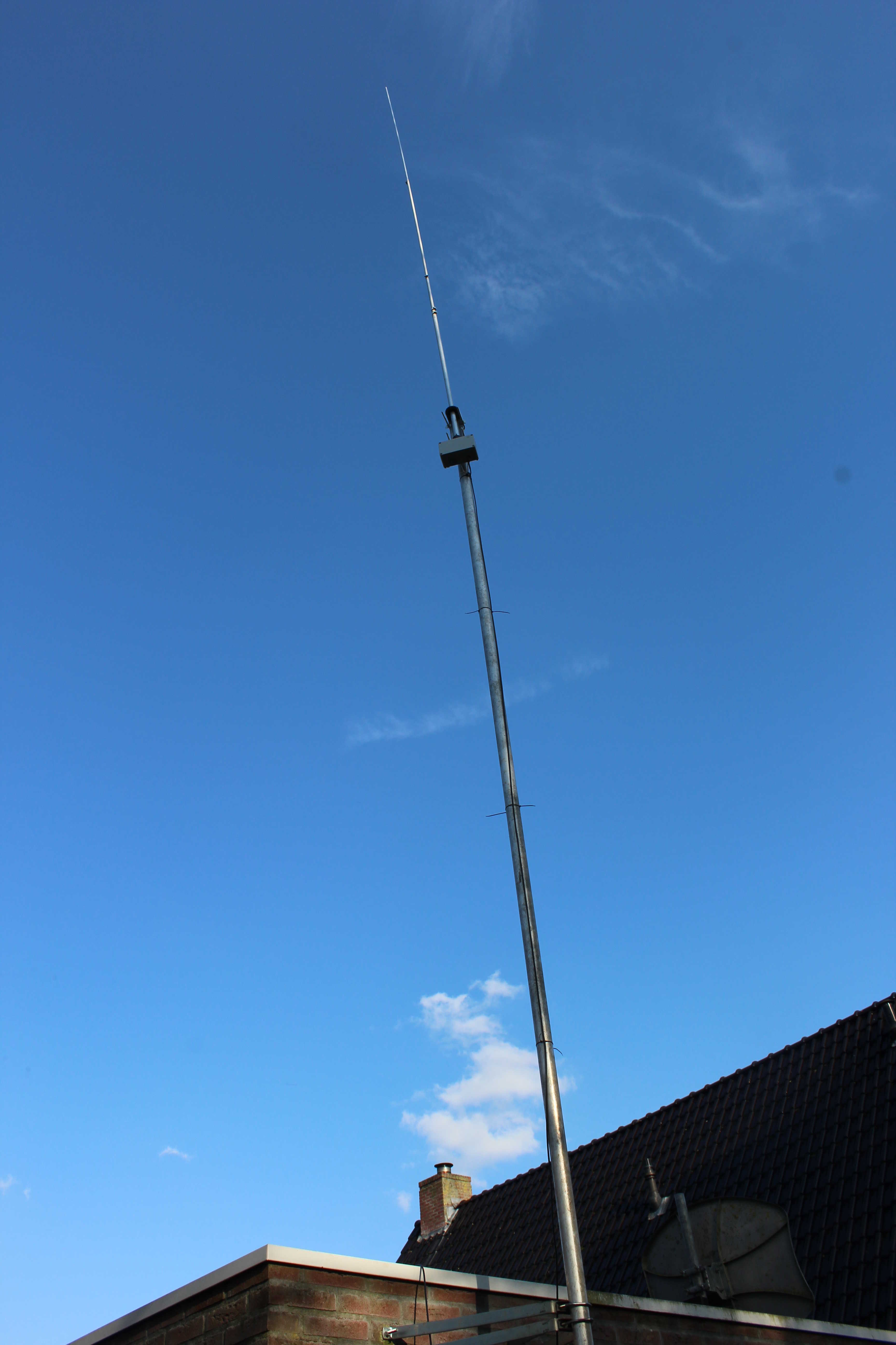
The 5/6/7 meters long antenna consist of 5 alloy pipes (1.5 mm and 1 mm thick):
22mm, 20mm and 17mm each 1.25 meters long,
15mm and 13mm each 2 meters long.
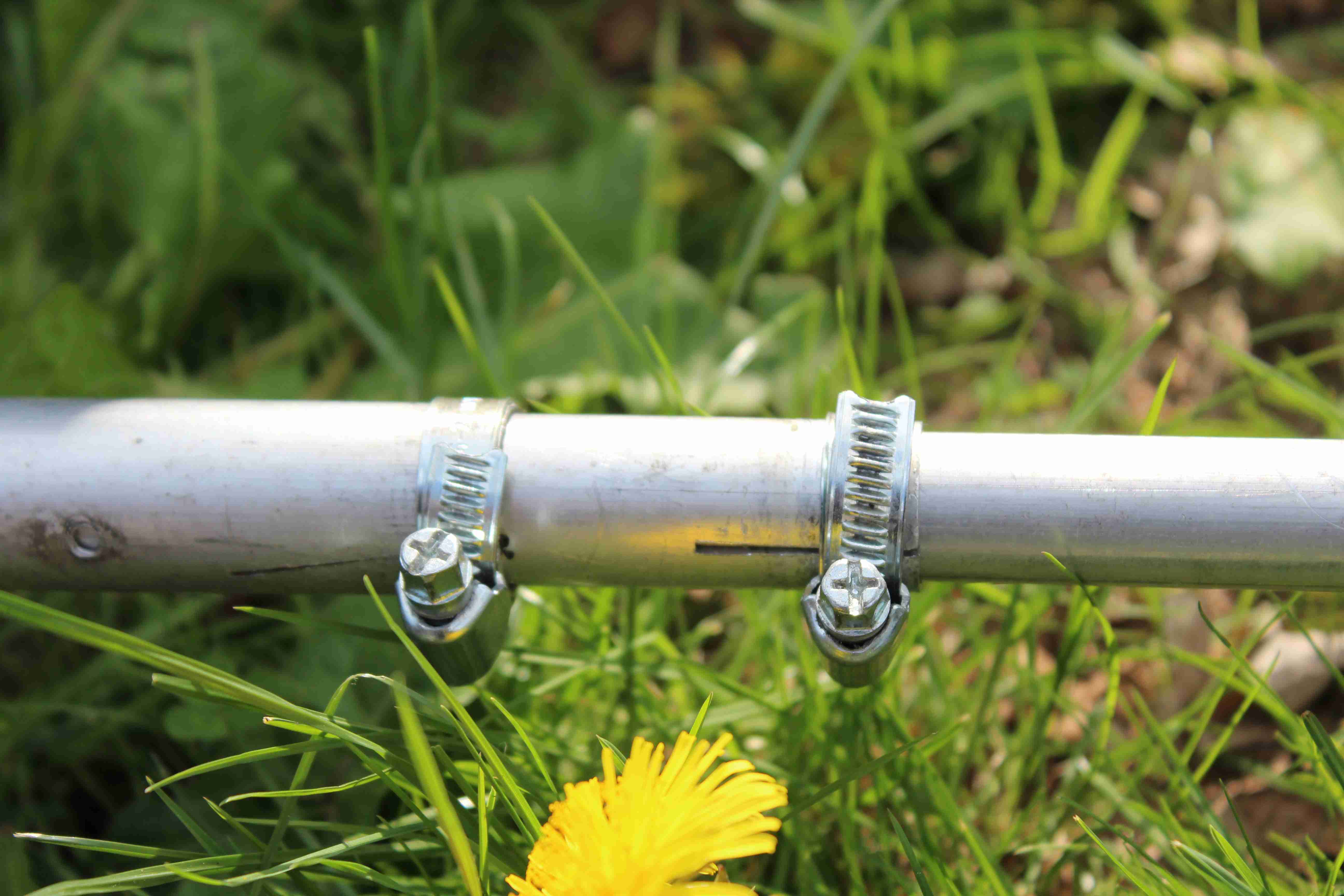
Hose clamps and a small cut
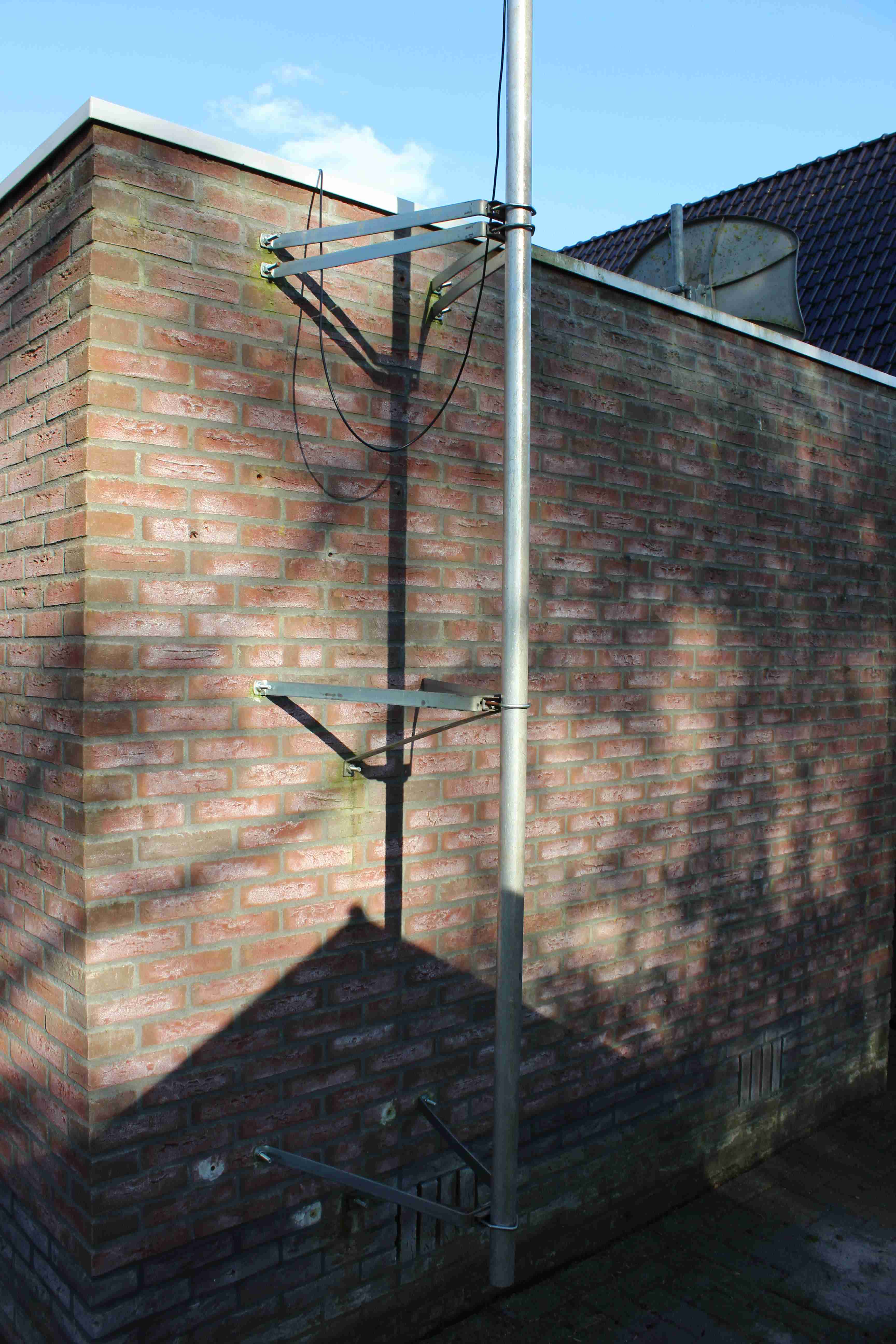
The antenna is mounted on a 6 meters alloy mast, the cable used is RG58U 20 meters long.
Twin feed
I liked to have an antenna that could be adjusted to any frequency. Coax-cable isn’t very forgiving for a bad SWR, it has a lot of loss, at first I tried a 300 Ohms symmetrical line and a transformer at the base. No common mode currents and no loss when you feed symmetric, a balun 4:1 at the base station and a unun 1:1 in the base of the antenna. This didn’t work well, making a good transformer wasn’t easy and needs more research.
Coax cable
The solution is to make a simple UNUN 4:1 transformer that transforms the antenna impedance to around 50 Ohms to work with a coax cable.
Unun
I ordered two toroids from Amidon. T130-2 and the T184-2, and used the T184-2, it has a higher Al value (240 µH/100 Wdg ) versus (110 µH/100 Wdg). Bigger cores tend to have higher Al values, also good can be the T200-2a or the T300-2 or T400-2. Where the T130-2 needs around 17 windings, does the T184-2 and the T200-2a only need 13 windings.
Kirchhoff’s law
The transformer forces (Kirchhoff law) the current in the antenna base to be low (almost zero), the voltage is transformed up two times. Low current gives less loss (skin effect). No current at the base means the antenna is endfed, in theory the impedance of a antenna is around 377 Ohms when the length is very long and very high above ground, you have to use a transformer to match. In practice using a 4:1 transformer gives a good impedance matching at low frequencies where the impedance will be much lower because the antenna impedance strongly depends on the length of the antenna, where the real part is around 40 Ohms and the total impedance is around 200 Ohms.
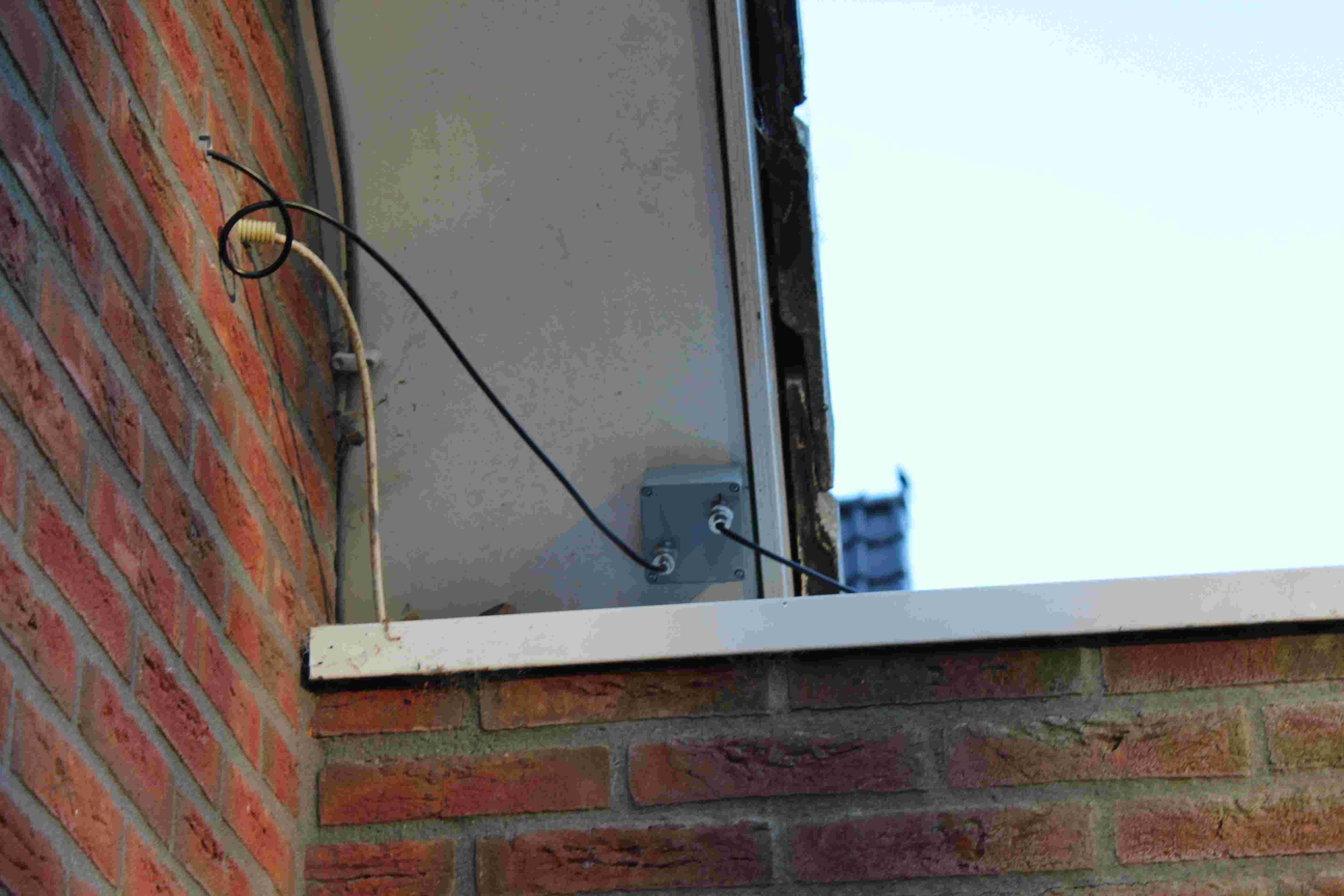
Common mode rejection
The
mast is isolated from earth. Current generated at the base can flow
back via the coax, this is called common mode current and will rise
noise and SWR at the transceiver. You need a common mode rejecter to
block this current, a simple method is to use the coax and make an
air coil (10 turns) at the base of the mast and at the transceiver,
the current should be blocked at the base of the mast at ¼ lambda
distance (d>2,5 meter) from the antenna. The most effective way is
a ferrite torriod with PTFE coax (rg178u) Amidon 240-43 core.
Coax cable length
The coax used for the first test was 25 meters long (RG58 V=0.66), this will give a wavelength of around 38 meters (25/0,66). If the cable is not matched by it’s typical impedance, this length will kick in. This cable length will due to it’s length generate possible mismatch problems at 20, 40 and 80 meters, energy that can’t be radiated by the antenna will resonate in the cable.
Antenna configuration
Two configurations
The antenna can be adjusted to any length,
the first setup is 5 meters of antenna and 25 meters of coax,
the second setup is 6 meters of antenna and 20 meters of coax.
the third setup is 7 meters of antenna and 18 meters of coax.
Antenna 5 meters long and 25 meters of coax RG 58 U.
Measurement of the SWR with the Kenwood TR-440S-at, the automatic antenna tuner in the Kenwood transciever turned off, some points were measured and a polynome calculated the missing points by a third order approximation, this will result in the graph. The SWR is below 4, the SWR is higher at transmit power than at low power (see Omicron bode 100 measurement below)
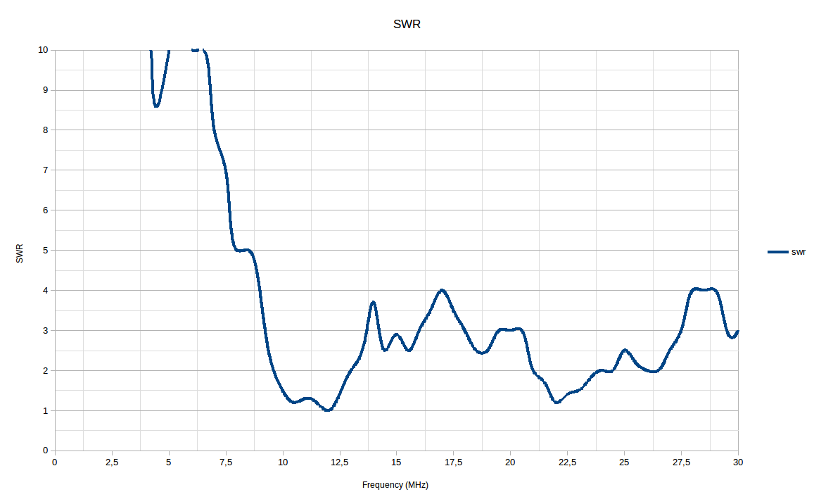
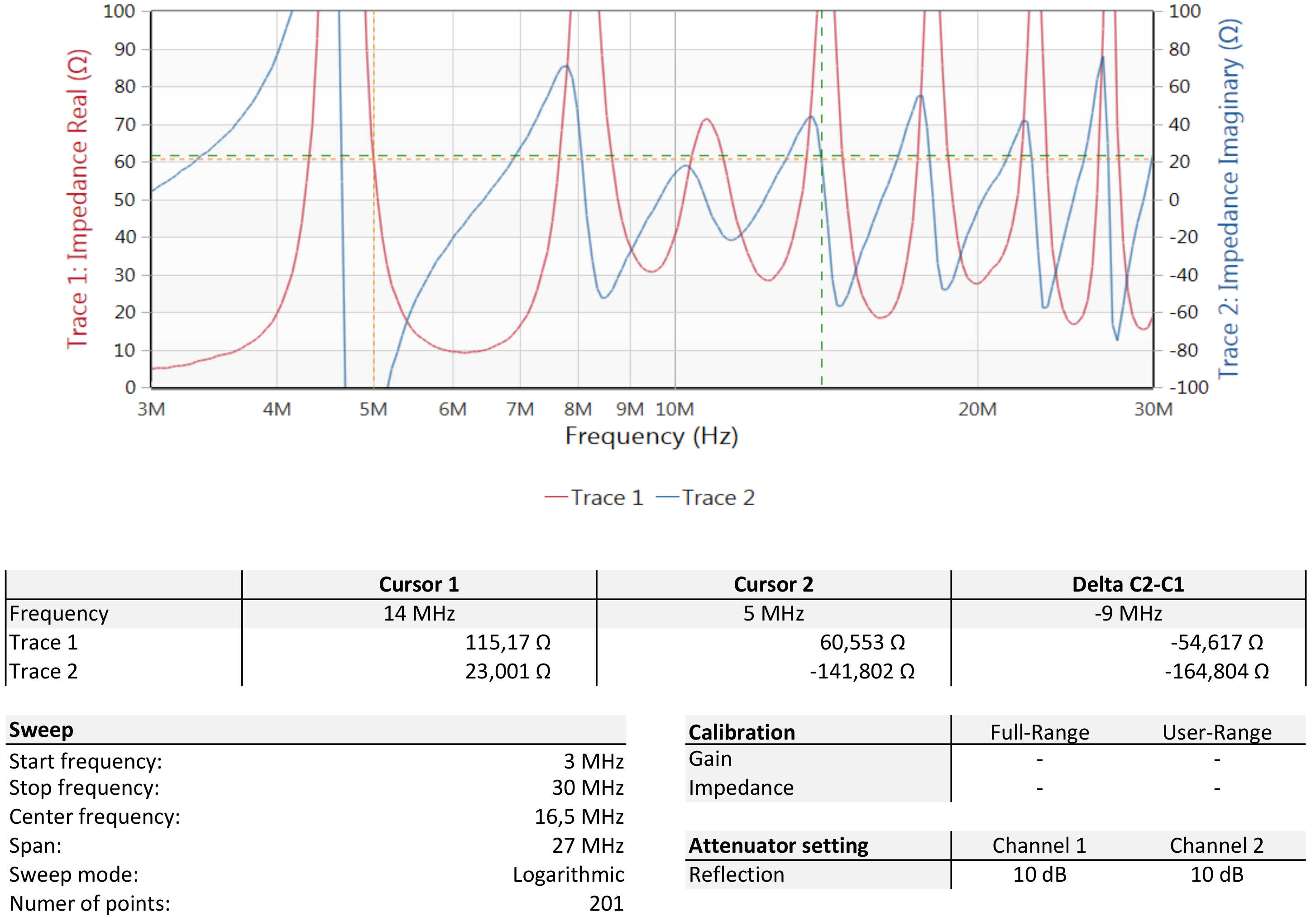
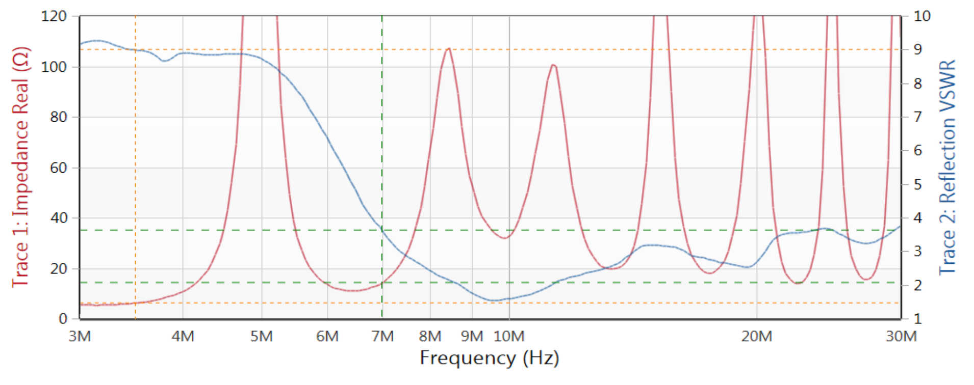
What is the effect of 25 meters cable and a 5m long radial?
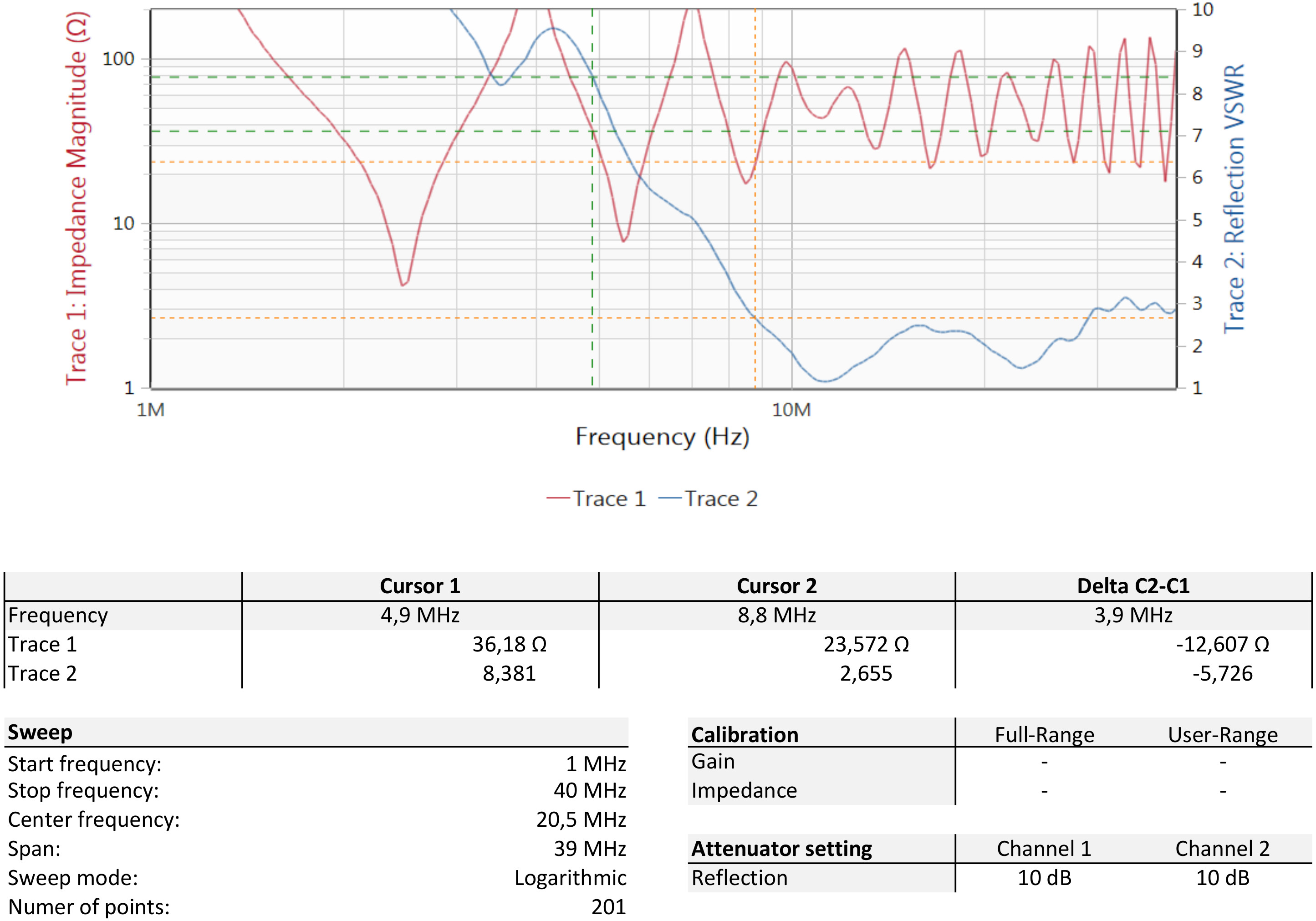
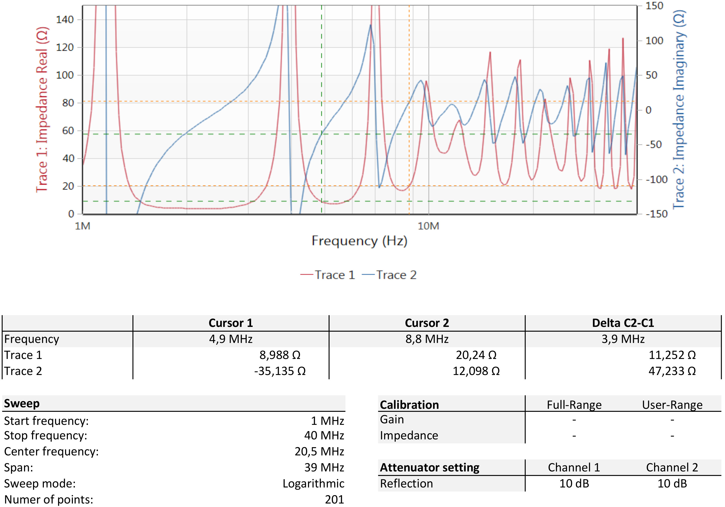
The next step is to measure more precise, I connected a Omicron bode 100 tester to the antenna and test the system including the cable. The effect of 25 meters cable, the antenna will not work on 3,5 and 7 MHz, the cable does resonate. You can see this be the increased level of real resistance, the real part is high.
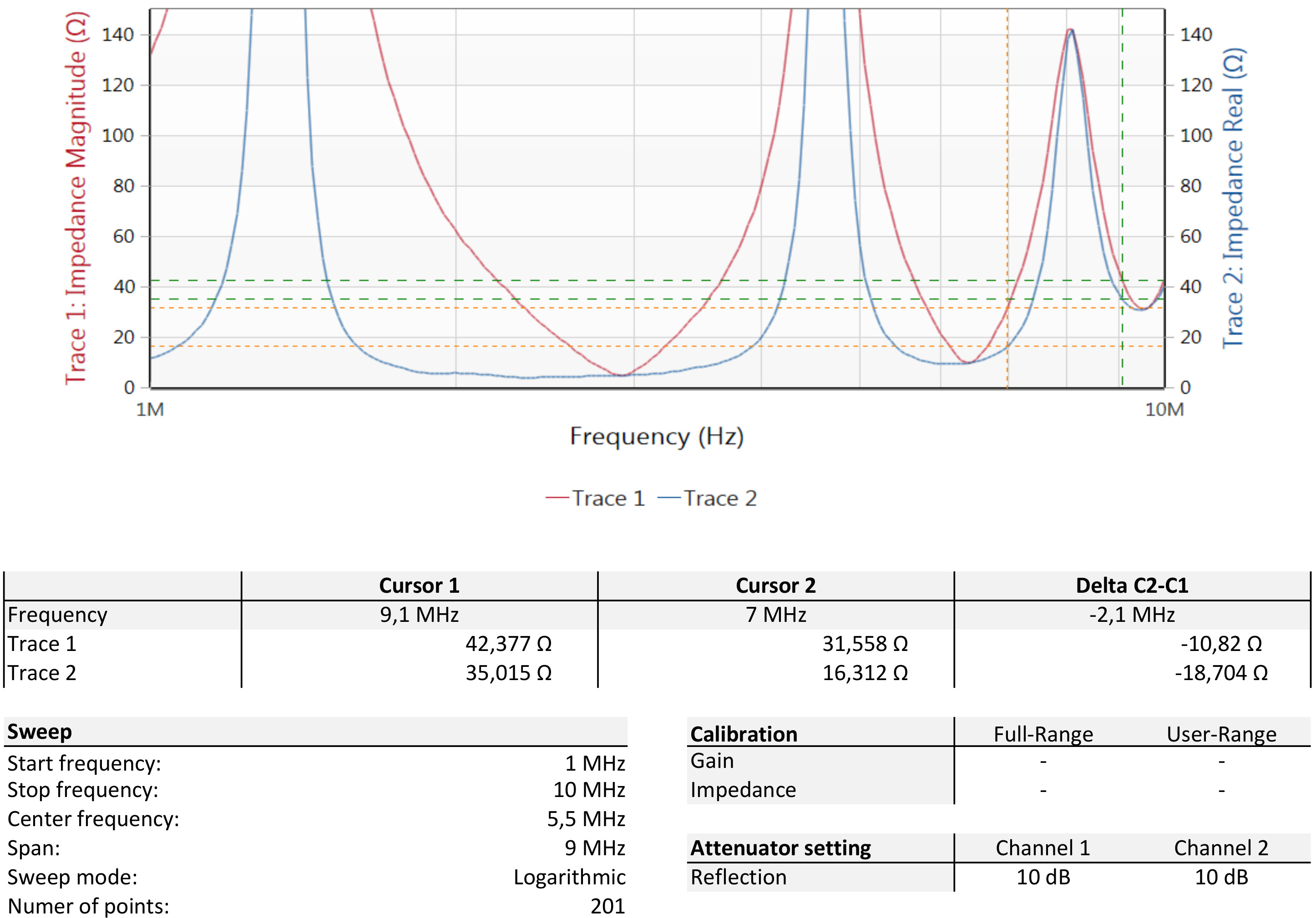
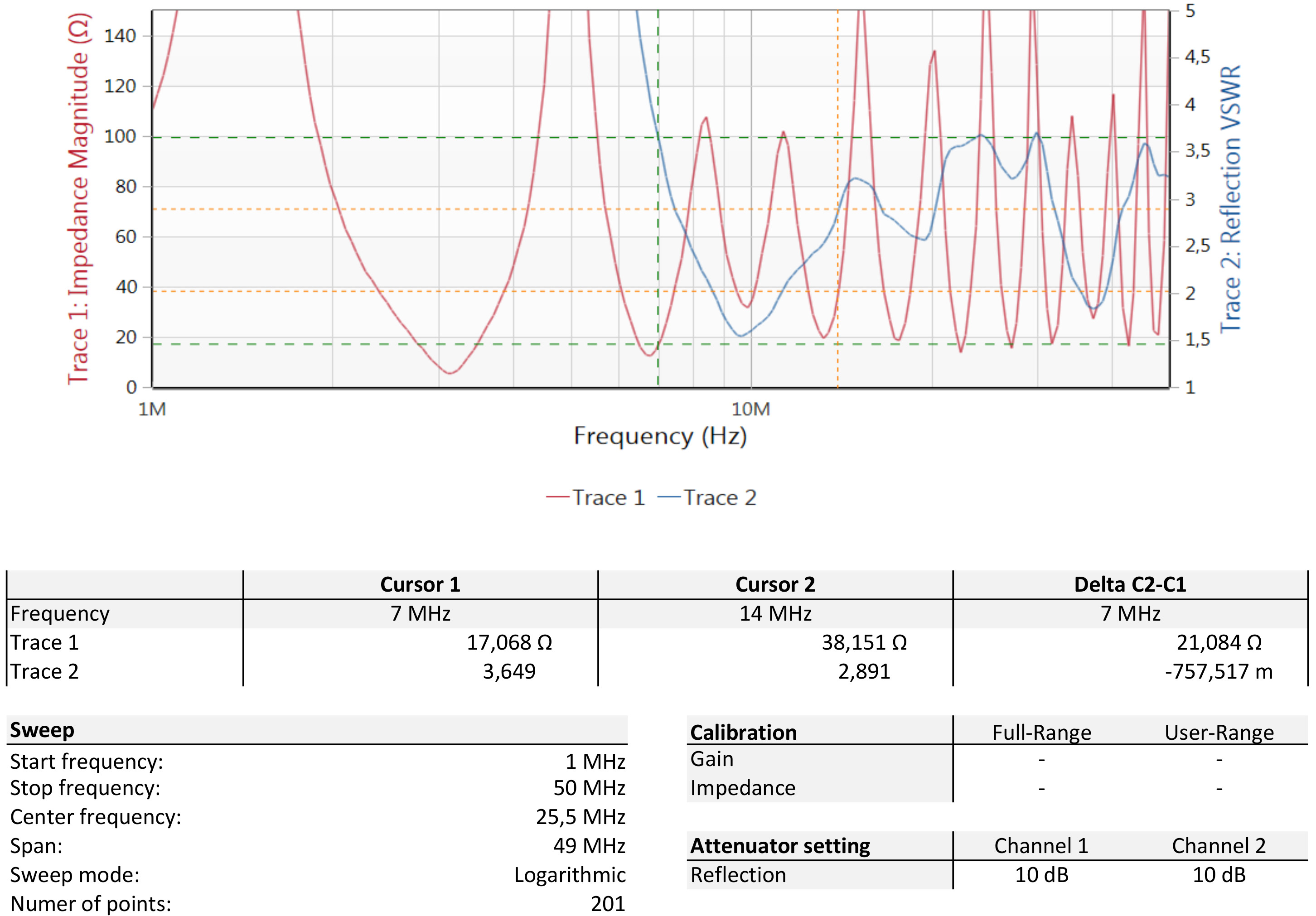
What is the effect of 20 meters cable and a 6m long radial?
Antenna 6 meters long and 20 meters of coax RG 58 U. The real part of the impedance is low at 3,6 and 7 MHz and the impedance is under 150 Ohms, the antenna can be matched easy with the build-in automatic tuner. The SWR is low from 10 MHz to 30 MHz, without using the tuner.
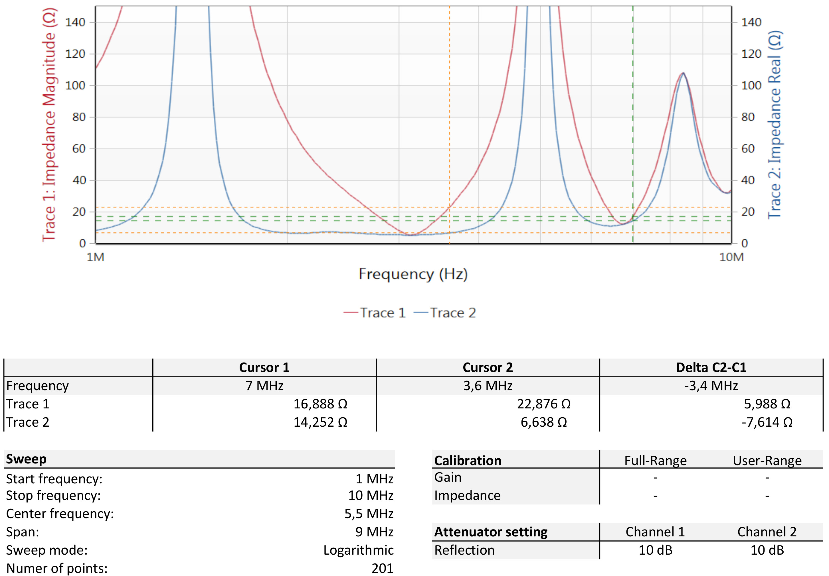
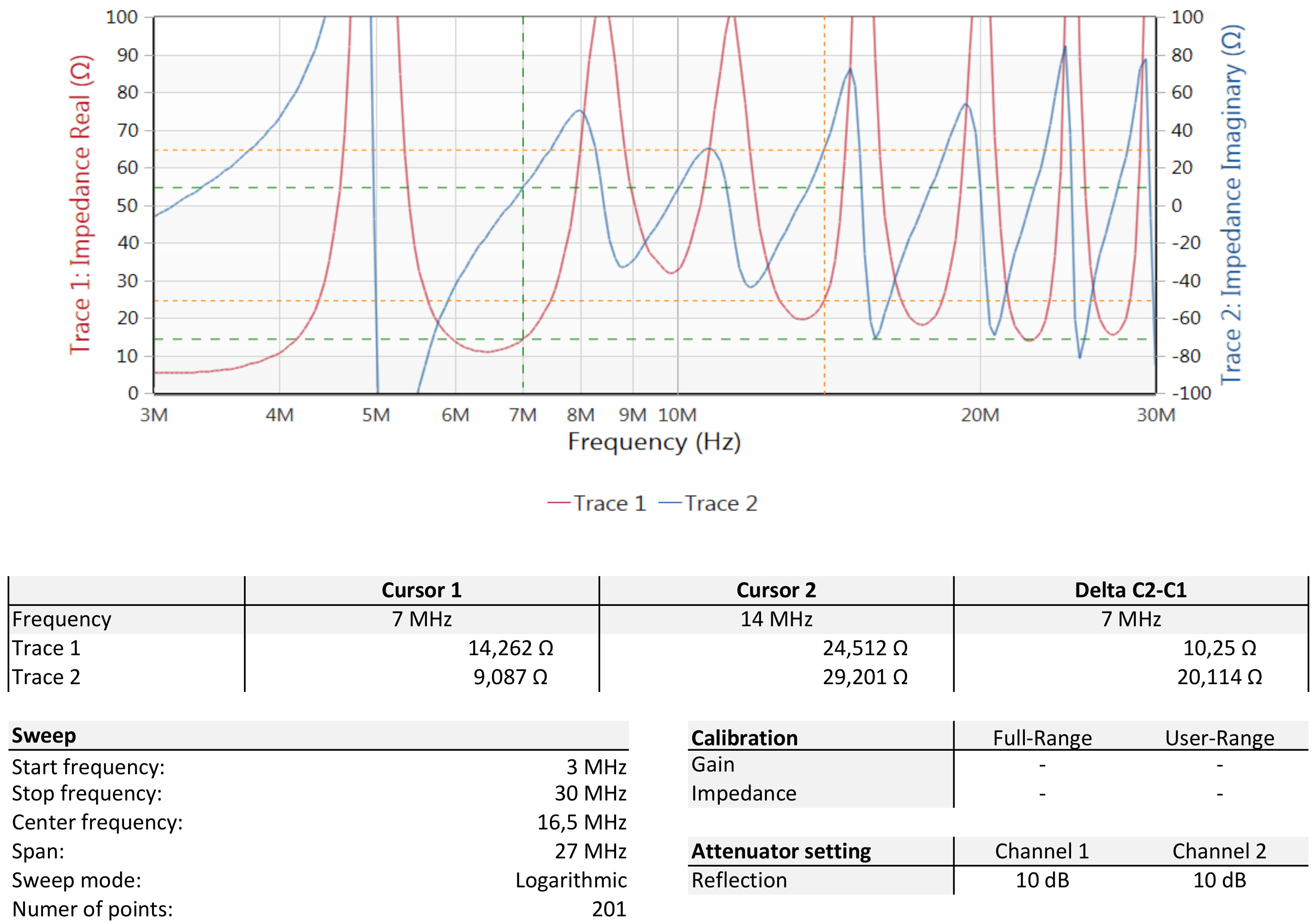
What is the effect of 18 meters cable and a 7m long radial?
Antenna 7 meters long and 18 meters of coax RG 58 U. The real part of the impedance is low at 3,6 and 7 MHz and the impedance is under 150 Ohms, the antenna can be matched easy with the build-in automatic tuner. The SWR is low from 10 MHz to 30 MHz, without using the tuner.
A summery of the results at September 2018
Feeded with 25 meter cable and 5 meter long radial, the SWR is low at: 10-11 and 22 Mhz.
Feeded
with 20 meter cable and 6 meter long radial, the SWR is low at: 10
and 21/42 MHz.
Feeded with 18 meter cable and 7 meter log
radial, the SWR is low at: 9.5 MHz and 19/38 MHz.
A shorter coax
cable makes the SWR at 20 MHz go higher, this means the coax has high
losses due impedance-mismatch.
A 7 meters long antenna has a
more appropriate real resistance at 3.6 MHz and 7.2 MHz, a longer
antenna is better at 3.6 MHz en 7.2 MHz.
Better for the
performance at the 40 and 80 meter band is a 7 meters long antenna.
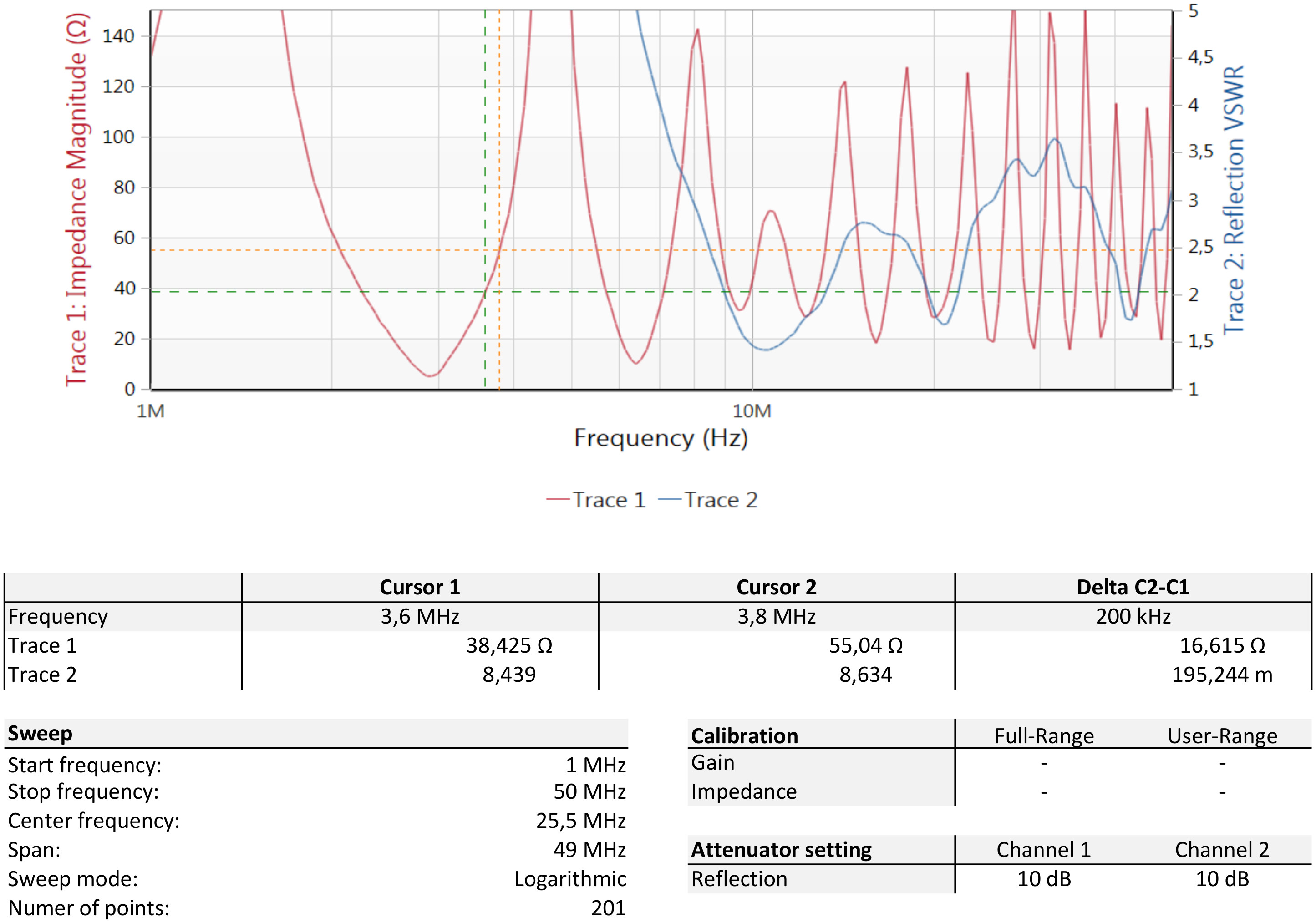
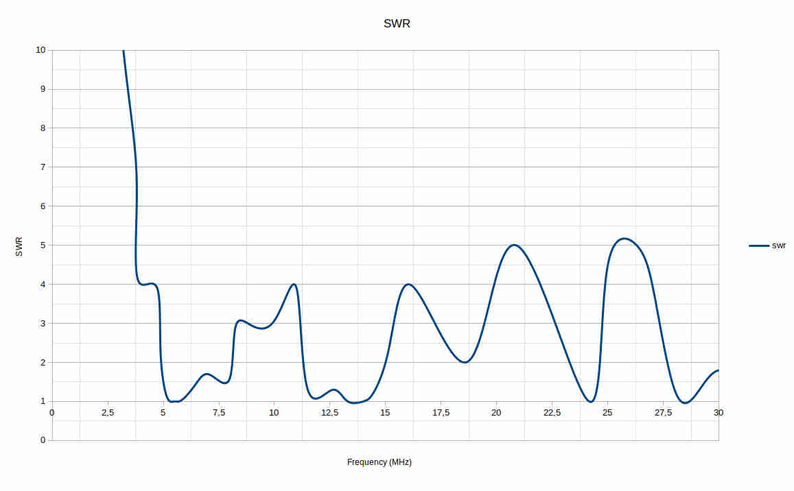
Below is the SWR graph of the 7 meter long antenna.
What to improve?
The graph plots a low SWR at the 9 Mhz and at 20 MHz, making the antenna 8 meters long the frequencies 7 MHz, 10 MHz and 14 MHz will improve in performance.
The construction
Two new vertical radials (2 x 3m long) were added and the loading coil at the base (inside the antenna base) was removed. A new transformer type UNUN 4:1 was added in a separate box at the base of the antenna.
The UNUN voltage tranformer 4 to 1:
Amidon toroid core type T 184-2
13 windings bifilair (see picture)
speaker cable for the 13 windings
epoxy encapsulated
The 8 meters long antenna consist of four alloy pipes (2mm, 1.5mm and 1mm thick):
22mm, 1.25m long, 1.5mm thick
20mm, 3m long, 2mm thick
17mm, 3m long, 1.5mm thick
15mm, 2m long, 1mm thick.
The antenna is mounted on a 11 meters steel mast, the cable used is RG213 15 meters and RG58U 5 meters long.
What is the effect of 20 meters cable and a 8m long radial mounted at a 11 meter mast?
To answer the question a SWR graph is made (see below), the difference is that the SWR is low at 60m, 40m, 20m, 12m and 10m band. These bands can now be used without an antenna tuner. The 80m, 30m, 17m and 15m band do still need some tuning to function well.
Call sign: PH1J
List of contacts:
Jelle Huitema
28 September 2020